Transmission electron microscope (TEM) study of graphite and diamonds in ureilites
- Abstract number
- 1154
- Event
- European Microscopy Congress 2020
- DOI
- 10.22443/rms.emc2020.1154
- Corresponding Email
- [email protected]
- Session
- PSA.6 - Geological Materials & Bio-mineral systems
- Authors
- Surya Rout (1), Jakob Storz (2), Addi Bischoff (2), Martin Ritter (1)
- Affiliations
-
1. Electron Microscopy Unit, Hamburg University of Technology
2. Institut für Planetologie, University of Münster
- Keywords
Meteorites
Ureilite
Transmission electron microscopy
Impact shock
- Abstract text
Introduction: Main-group ureilites predominantly consist of olivine and pyroxenes and are considered to represent the mantle of a partially melted, carbon-rich asteroid [1]. The bulk carbon contents in ureilites can go up to ~8 wt% and the carbon-bearing phases are predominantly graphite and minor diamonds. The origin of diamonds in ureilites is controversial and there are three different hypotheses: (a) impact shock-induced transformation from graphite [2]; (b) chemical vapor deposition [3]; (c) formation under high static pressures inside a planetary body [4]. Recently, [4] proposed that diamond in ureilites formed at ~20 GPa inside a Mercury- to Mars-sized planetary body, but these authors did not explain the absence of other high-pressure minerals in these rocks. Here we studied diamond and graphite from high and low shocked ureilite meteorites in order to better understand the formation process of diamonds in ureilites.
Materials & Methods: Five ureilitic samples from the brecciated Almahata Sitta meteorite were selected for this study [5]: MS-MU 27, MS-MU 006, MS-MU 045, MS-170, MS-187. While MS-MU 006, MS-187, and MS 170 are of low-shock degree, MS-MU 027 and MS-MU 045 are severely shocked. Graphite and graphite-diamond aggregates were identified and studied using optical microscopy, Raman spectroscopy, and cathodoluminescence at the University of Münster. Samples for transmission electron microscopy (TEM) were prepared from graphite and graphite-diamond aggregates using conventional in situ lift-out technique using a Helios NanoLab G3 focused ion beam/scanning electron microscope (FIB-SEM). A total of five lamellae were prepared and studied using a Talos F200X TEM operating at 200 kV.
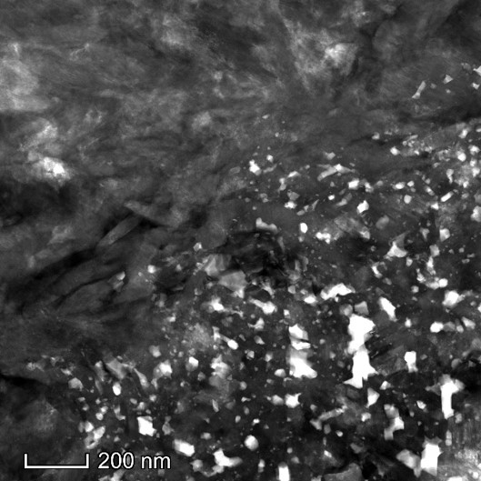
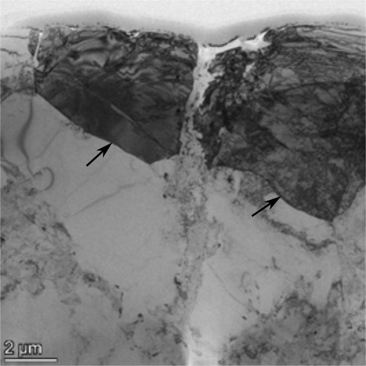
Results and Discussion: Graphite from low shocked AHS MS-MU 006 is well-crystalline and does not contain any inclusions of diamond. A large (>100 µm) diamond-rich graphite from MS-MU 27 was selected for our study and a C-rich FIB-prepared lamella shows the presence of two different types of regions (Fig. 1): (a) nano-polycrystalline region with high density of dislocations; (b) polycrystalline region with many inclusions of Fe-Ni metal, chromite, (Fe,Ni)-phosphate, and (Fe,Ni)-sulfide (Fig. 2). The nano-polycrystalline region consists of minor cubic diamond and high concentration of lonsdaleite, a cubic diamond with extensive twins and stacking faults [6]. The inclusion-rich polycrystalline region consists of cubic diamond and minor lonsdaleite. Similar nano-polycrystalline diamonds are also seen in gneiss inclusions within impact melt rocks of the Popigai impact crater [7]. Nano-polycrystalline diamonds form under high pressure through martensitic transformation from well-crystalline graphite grains. The FIB-prepared lamella from an aggregate of graphite-diamond in the ureilite MS-170 contains large crystals of diamond with high dislocation densities (Fig.1). The diamond crystals are separated by bands of graphite as seen by [4] and the diamond and graphite grains have numerous inclusions of Fe-Ni metal, chromite, (Fe,Ni)-phosphate, and (Fe,Ni)-sulfide (Fig. 3). Nano-polycrystalline diamonds within MS-MU 027 most likely formed due to an impact shock event, which also disrupted the ureilite parent body. However, the studied diamond in MS-170 is not similar to the nano-polycrystalline diamond seen within MS-MU 027 and we are doing further studies in order to understand its origin.
Figure 1: Scanning transmission electron microscope-high-angle annular dark-field (STEM-HAADF) image of diamond from MS-MU 27 sample (left). The interface between nano-polycrystalline diamond and the inclusion-bearing (bright regions) diamond can be clearly seen. Bright-field TEM image of C-rich lamella fom AHS MS-MU 170 (right) showing large diamond crystals (indicated by arrows).
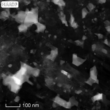
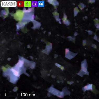
Figure 2: STEM-HAADF image (left) of a region within the TEM lamella prepared from MS-MU 27 (left image in Fig. 1). Energy dispersive spectroscopy (EDS) spectrum image (SI) from the same region (right).
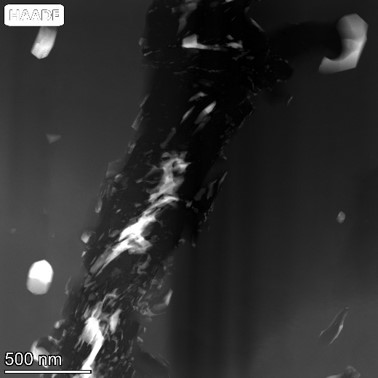
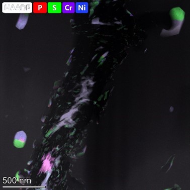
Figure 3: STEM-HAADF image (left) from a region within the TEM lamella prepared from AHS MS-MU 170 (right image in Fig. 1) and SI from the same region (right).
- References
References: [1] C. A. Goodrich et al, Met. Planet. Sci. 50 (2015), p. 782-809. [2] A. Bischoff et al., 30th Lunar Planet. Sci. Conf. (1999), Abstract # 1100. [3] K. Fukunaga et al., Nature 328 (1987), p. 141-143. [4] F. Nabiei et al, Nature Commun. 9 (2018), 1327, p. 1-6. [5] M. Horstmann and A. Bischoff, Chem. Erde 74 (2014), p. 149-183. [6] P. Neméth et al, Nature Commun. 5 (2014), 5447. [7] H. Ohfuji et al, Sci. Rep. 5 (2015), 14702.